

News


Flow control in immersion lithography
For more than ten years, immersion lithography has been the main exposure technology in semiconductor manufacturing. Compared to traditional dry lithography methods, this technique greatly improves the exposure resolution by injecting a high-refractive index liquid into the gap between the lens and the wafer surface. Maintaining the purity and uniformity of submerged liquid and avoiding the formation of residual droplets in the process of high-speed scanning are two major challenges facing the development of submerged lithography technology. Contaminants, particles, bubbles, heating and stress in the liquid can disrupt the continuity of the refractive index. The high-speed movement of the wafer during scanning may destabilize the meniscus at the interface between the liquid and the surrounding gas, resulting in residual droplets on the wafer. The above phenomena will affect the exposure performance of immersion lithography, and the corresponding flow behavior control method is needed to solve the problem.
1, Influence of flow behavior control on liquid purity and uniformity
1.1. Influence of flow behavior on liquid purity and uniformity
1.1.1. Particles and contaminants
Particles and contaminants are the main sources of solid impurities in submerged liquids. Particles suspended in an immersed liquid near the wafer surface or on top of the photoresist can be imaged into the underlying photoresist or transferred into the photoresist during development.
Particles may be present in the liquid supply or may come from any surface the liquid touches. First, the liquid used for immersion inevitably contains particles and impurities, so clean room deionized water is used as the immersion solution and it is further treated and filtered before injection into the immersion head. Another particle problem is the peeling of the film around the wafer bevel, which is caused by insufficient adhesion between the bevel surface and the surface coating. During exposure, these particles can be transported back and forth through the liquid meniscus from the wafer edge to the wafer center. Methods to solve this problem include selection of photoresist, optimization of EBR formulation, and wafer processing. Wafer pads are also a potential source of particles. As the submerged head moves across the wafer, the submerged head picks up particles and redeposits them. Conventional cleaning of the wafer table will reduce the number of particles, and in-situ cleaning technology has been proven to be a very effective field cleaning method. Other defects caused by transparent photoresist/topcoat particles deposited on the surface of the photoresist or topcoat film (as anti-bubble defects) can be reduced by optimizing the coating formulation.
The effective way to solve the leaching problem is to use a low leaching rate of the resist or top barrier layer. Rinsing resist films with deionized water has also been investigated as an alternative to the leaching problem. In addition, the submerged head area is larger than the exposure field area, which means that the wafer is soaked before and after exposure, as in the flushing process [38]. Since the liquid continues to flow through the submerged head during exposure and immersion, the contaminants in the submerged liquid will be greatly removed and can therefore replace the flushing process.
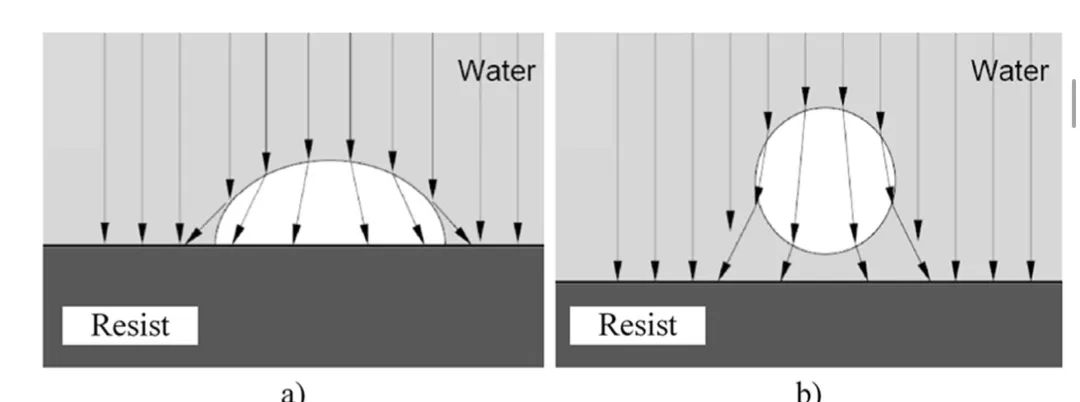
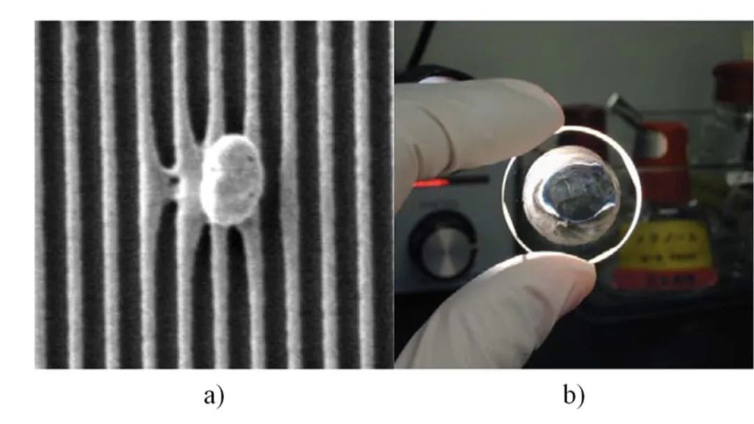
Bubbles reflect and refract incoming light. a) on the surface of the photoresist, and b) floating in the immersed solution.
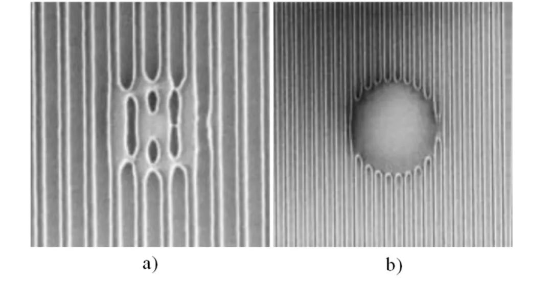
Defects of bubbles of different sizes. a) 0.85μm, b) 3μm.
1.1.2. Bubble
One of the main challenges of bubble immersion lithography is the requirement that no bubbles appear in the immersion solution during the exposure process. The curved gas-liquid interface caused by bubbles reflects and refracts incident light, which creates refractive index discontinuities and increases scattering effects, ultimately resulting in defects in the pattern and reduced yield.
The main factors that affect the effect of bubbles are exposure time, bubble size, and the height of the bubbles above the wafer, with shorter exposure times enhancing the effect of bubbles, causing features to stay in the more heavily shadoed area for more exposure time. Second, if the bubble is the same size as the wavelength of the light used for exposure, the light scatters and increases stray light. If the bubble size is micrometers or larger, the bubble will partially block and change the direction of light. Finally, the study also found that the overall effect of the bubbles on the image depends on the distance of the bubbles from the wafer surface - the greater the distance, the weaker the effect, as bubbles away from the photoresist can be quickly washed away in a fast-moving fluid. If the ratio of the bubble's distance from the wafer to the bubble's diameter is 4:10, the effect of a single floating bubble is negligible. As the bubble gets closer to the wafer, due to the slower fluid flow near the wafer surface, the bubble's shadow in the image plane becomes stronger and its lifetime at a certain location on the wafer becomes longer. As a result, bubbles attached to the wafer surface pose a much greater threat to a defect-free image. Through the systematic study of bubble scattering effect in submerged lithography, it is predicted that 60nm is the maximum bubble size that will not cause defects when the bubble is attached to the surface of the photoresist. The bubbles in submerged lithography may be caused by the interference of various factors such as pressure, temperature, photochemical reaction and fluid dynamics.
1.1.3. Heating
During exposure, the immersed liquid is heated unevenly, and the temperature distribution may affect the image in a number of ways, while also producing small amounts of spherical and higher-order aberrations, and the main imaging defect is defocus. If we only allow a defocusing amount of 1 nanometer, the refractive index change needs to be kept very small. Since the temperature coefficient of water (dn/dτ=-10-4K-1) is very large compared to the gas, the liquid temperature needs to be kept within 10 mK, which places strict limits on liquid handling and temperature control systems.
1.1.4. Stress
For immersion lithography, the high viscosity and high density of the immersed liquid, compared to air in dry lithography, can cause significant stress on both the lens and wafer surfaces. These normal and shear stresses can lead to lens distortion and birefringence, thus disrupting the uniform light path.
1.2. Control methods
There are three ways to reduce the above behaviors that affect exposure performance. To avoid impurities and bubbles from the exposure process,
In Section
1.2.1 low leaching and low gas release photoresist are used. In order to prevent bubbles and particles from imprinting on the wafer, Section
1.2.2 describes the specific wiring method and the thick coating method. Finally, to balance the temperature and stress distribution by carrying contaminants, particles, bubbles, and heat away from the exposure area,
Section
1.2.3 uses liquid supply and recovery methods.
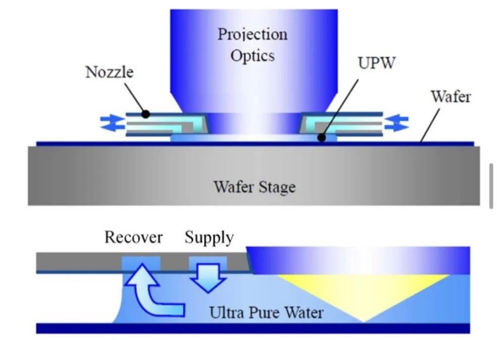
Nikon was the first company in the world to develop an ArF immersion scanner for production, the NSR-S609B [75]. Prior to this, they had made many attempts at submerged head structures based on the local fill method. They simulated the local filling method with and without liquid supply and recovery system [54,67] and found that the liquid supply and recovery system also acted as a liquid containment structure. In the absence of a supply and recovery system, some of the liquid is located outside the lens area, with some empty space below the lens area. In the presence of a feed and recovery system, the recovery flow strengthens the surface tension at the gas-liquid interface around the liquid pit, successfully confining the liquid to a local area below the lens, showing better liquid containment.
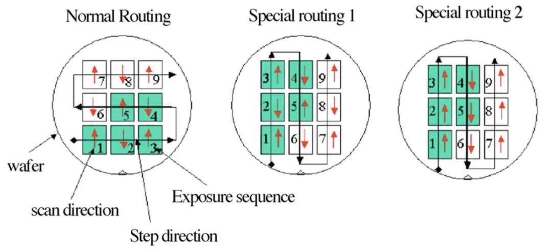
Normal wiring and 2 special wiring to reduce defects
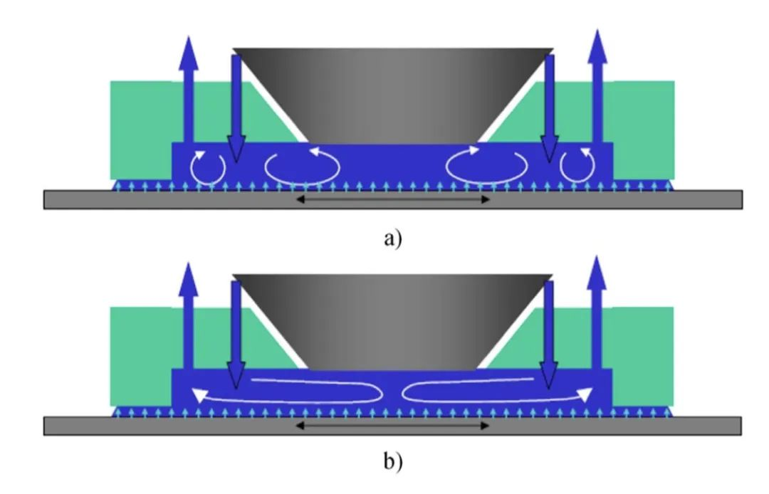
Two different nozzle arrangements. a) Older generation nozzle; b) New nozzles.
Basic structure of LLF immersion system.
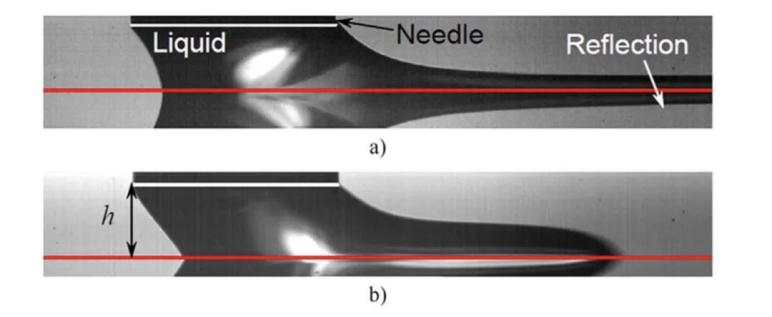
A typical meniscus shape. a). Film stretching, b). Inertial overflow.
2. Flow behavior control of meniscus stability
2.1. Meniscus instability and residual droplets in immersion lithography
Throughout the process, the fluid must remain within the gap between the last optical lens and the wafer. As the wafer moves beneath the liquid, viscous forces begin to pull the liquid toward the scanning direction and affect the meniscus. Beyond a certain speed, the stability of the receding meniscus is disrupted, and the liquid is pulled out of its liquid volume and subsequently broken down into droplets. These residual droplets can remain on the wafer and cause numerous image defects. Now in the semiconductor industry, the scanning speed of mass manufacturing is 800mm/s, and it will be higher in the future. Therefore, it is necessary to ensure that the meniscus of the submerged field does not lose stability within this velocity requirement.
2.2 Basic research on meniscus stability
Critical velocity refers to the maximum velocity that can be achieved without depositing residual liquid, and is a very important performance parameter in immersion lithography. Through the "drag drop" experiments on 41 different photoresist [80,87,88], the results show that the critical velocity increases significantly with the increase of the static recessional contact Angle, both in the film drawing state and in the inertial overflow state.
2.3. Control methods
There are three ways to reduce residual droplets on the wafer. In order to improve the stability of the meniscus and avoid the formation of residual droplets during exposure, more hydrophobic photoresist can be used in immersion lithography. In order to remove the residual droplets that have just left the meniscus, an air curtain and a porous medium are used. In order to control the flow rate of liquid near the recovery channel and facilitate recovery function, surface modification based on heterogeneous surfaces with wettability contrast can be applied to the submerged head.
2.3.1. The hydrophobicity of the modified dome surface controls the speed of wafer scanning and exposure. Higher hydrophobicity means a higher static receding contact Angle, which makes it easier and faster for the submerged liquid to move across the wafer without leaving behind residual droplets. Higher hydrophobicity is therefore key to maximising throughput and, when combined with lower defect rates, can also increase yields.
2.3.2. Second liquid containment method
Another way to control the stability of the meniscus is the special design of the submerged head. Taking into account the different contact angles between different resist and finishes and the submerged liquid, the submerged head structure must be able to achieve a wide operating range at high scanning speeds. ASML reports that using the new submerged head significantly reduces total defects (more than 3x) when the scan speed is 600 mm/s.
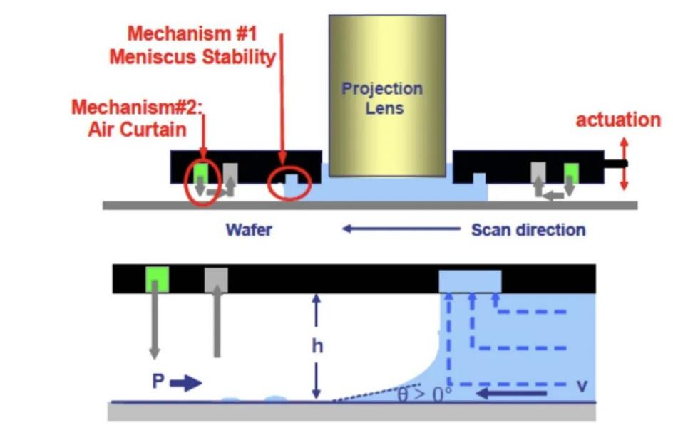
The most common optimization for submerged heads is the air curtain structure. This design creates a high-pressure air curtain around the submerged area, keeping the fluid in the gap below the last optical element.
2.3.3. Surface modification of submerged head
The above surface modifications for meniscus stability control are all applied on wafers and are based on homogeneous surfaces, but heterogeneous surfaces with wettability contrast can also be used to accommodate the liquid in the gap. Considering that the actual lithography process may not allow the heterogeneous modification of the resist surface, this method can be applied to the submerged head.
Fountyl Technologies PTE Ltd, is focusing on semiconductor manufacturing industry, main products include: Pin chuck, porous ceramic chuck, ceramic end effector, ceramic square beam, ceramic spindle, welcome to contact and negotiation!